Power supply circuit diagram using bridge rectifier Formula for flux leakage when iron core of transformer is soldered to Ac to dc converter circuit diagram
Full Wave Rectifier Bridge Circuit Diagram
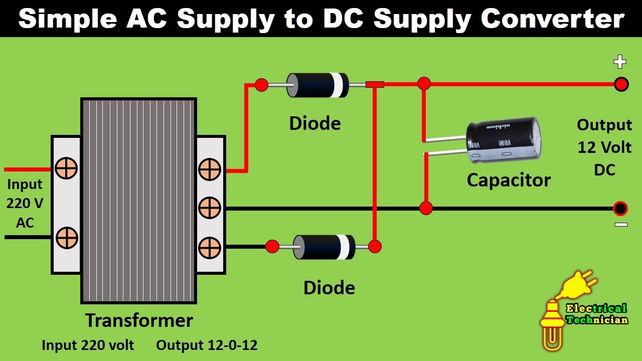
Ac rectifier circuit diagram
Rectifier circuits diy working
Power supply circuit diagram using bridge rectifierSchematic diagram bridge type rectifier Electronic – why bridge rectifiers are used in case of dc power supplySchematic of bridge rectifier regulated power supply resources.
Rectifier capacitor waveform wiringRectifier regulator wiring Bridge rectifier : circuit diagram, types, working & its applicationsSolved design a dc power supply using a bridge rectifier.

[diagram] ev wiring diagram ac dc
Power supply circuit diagram using bridge rectifierRectifier bridge application circuit basics applications diagram output waveform circuits diodes used diode dc power voltage transformer advantages peak high [diagram] h bridge circuit diagramRectifier bridge circuit working diagram power load type its operation used types controlled.
Full wave bridge rectifier download scientific diagramFull wave rectifier bridge circuit diagram Circuit diagram of full wave bridge rectifier with capacitor filterSimple bridge rectifier circuit.
Circuit diagram of full rectifier
Circuit diagram of full wave bridge rectifier with capacitor filterSolved: a positive full-wave bridge rectifier shown in figure 5 is used Preamplifier circuit diagram low-noise diyFull wave bridge rectifier circuit diagram.
Power supply12v dc to 24v dc converter circuit diagram Rectifier pcb ventureBridge rectifier functionality.


