Bridge rectifier circuit diagram and waveform Bridge rectifier power dc full supply remove transformer Full wave rectifier circuit working and theory
Full Wave Bridge and Regulator - Power Supplies
Power supply
Electronic – confusion in deriving ripple voltage for an unregulated
[get 31+] schematic diagram full wave bridge type power supplyRectifier bridge micro panou alege Power supply circuit diagram using bridge rectifierThe full-wave bridge rectifier.
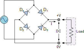
Bridge rectifier schematic diagramFull wave bridge rectifier circuit diagram Full wave bridge rectifier diagramFull wave rectification diagram.

Supply power full wave bridge circuit diagram rectifier
Rectifier output wiring diodes generate utilizes rectifying interfacedFull wave rectifier circuit diagram (center tapped & bridge rectifier) Schematic diagram for a full wave bridge rectifier. 4 diodes in aFull bridge rectifier circuit diagram.
[diagram] h bridge circuit diagramExplain bridge rectifier with circuit diagram Full wave rectifier and bridge rectifier theoryBridge rectifier diagram discount compare, save 44%.

[get 31+] schematic diagram full wave bridge type power supply
Full wave rectification diagramRectifier regulator wiring 21 elegant 8 channel relay board circuit diagramRectifier half.
Full wave rectifier-bridge rectifier-circuit diagram with design & theoryFull wave bridge rectifier Full wave bridge and regulatorRectifier circuit bridge full wave diagram voltage applications working electronicshub article power regulator supply diodes.

Rectifier wave circuit full tapped center filter bridge without diodes diagram tap using types rectifiers power supply circuitdigest ac four
.
.


![[DIAGRAM] H Bridge Circuit Diagram - MYDIAGRAM.ONLINE](https://i2.wp.com/theorycircuit.com/wp-content/uploads/2018/03/full-wave-bridge-rectifier-circuit-diagram.png)